
Type II mechanoreceptors and cuneate spiking neuronal network enable touch localization on a large-area e-skin
作者:Oddo, Calogero Maria
Main
The tactile sense is essential to perceive and process information about the surroundings, allowing humans to establish social interactions, locate and react to external stimuli, and recognize features of what is being touched1,2,3,4,5. In addition, touch is fundamental for body preservation, through the identification and localization of innocuous contact events and harmful stimuli, enabling dexterity with fine control of touching behaviours and preventing damages and accidents3,6. This abundance of tactile information reflects the variety of tactile receptors that populate the human skin. Mechanical stimuli are, in fact, encoded by four main classes of primary afferents (PAs), also known as mechanoreceptors, that innervate glabrous skin. These mechanoreceptors are distinguished according to their adaptation to different stimuli. Slowly adapting receptors have a sustained response during the overall duration of the stimulus, whereas rapidly adapting receptors respond primarily to transients, such as the beginning or the end of an applied mechanical stimulus2,7,8. In addition, mechanoreceptors can be classified into two classes according to their location within the layers of the human skin. Type I mechanoreceptors present small receptive fields and are located near the epidermal surface. Among them, there are Merkel discs and Meissner corpuscles, which are slowly adapting type I (SAI) and fast-adapting type I (FAI) units, respectively. Conversely, Ruffini and Pacinian corpuscles are classified as slowly adapting type II (SAII) and fast-adapting type II (FAII) receptors, respectively, being located deeply in the dermis and having large receptive fields with obscure borders2,9,10. The cooperation of all these receptors fosters a human’s ability to recognize and localize light and heavy touch, sustained pressure, vibrations, textures and fine features. The artificial implementation of these functionalities would be desirable in both industrial and biomedical applications in which awareness of the surroundings is a major requirement. As an example, collaborative robots need to interact safely with the environment and humans in various scenarios11,12,13, and users of bionic prostheses or exoskeletons would benefit from enhanced tactile information for a better embodiment and control of the artifacts14,15,16.
Thus, the development of biomimetic tactile systems, enriched by a thorough understanding of somatosensory learning mechanisms, would make it possible to equip robots with sensing devices capable of generalizing and adapting to new stimuli and develop more intuitive functional bionic devices for the restoration of sensory channels14,17,18. These needs have driven numerous research studies and the development of tactile sensors, based on electronic technologies, such as piezoresistive and capacitive elements, to implement bioinspired artificial skins3,11,17,19,20. Nevertheless, the deployment of these systems is still limited since they do not feature either the physiological skin shape flexibility and sensitivity distribution, given their rigid substrates and wiring issues, or the natural mechanism of efficient tactile information decoding4,11,13,21. Recently, fibre Bragg grating (FBG) sensors have proven to be a viable alternative for developing bioinspired e-skins, owing to their multiplexing properties, that is, the possibility to distribute multiple sensing units along a single optical fibre11,22. FBGs deeply placed in a silicone layer resembling human skin were proven to functionally mimic Ruffini mechanoreceptors, enabling the decoding of stimuli applied onto the e-skin by means of supervised learning methods11. However, biomimetic intelligence and the efficiency of somatosensory processing are still lacking in these systems, possibly because these biological mechanisms have not been completely and thoroughly understood yet21,23,24,25.
Currently, several models of tactile processing are based on analogies with vision due to its spatial accuracy21,26. However, touch sense mechanisms also present high temporal precision, with sensitivity to different frequency ranges, as it happens in the auditory system21,23,27,28. Recently, two bioinspired models have been proposed in tactile somatosensory computing for the classification of textures29 and edge orientation30. These models implemented a PA spike-time-dependent synaptic learning and a functional organization of the receptive fields of the higher processing structures inspired by the cuneate nucleus and somatosensory cortex, respectively. However, to the best of our knowledge, there are no artificial biomimetic models in the literature that combine both paradigms—temporal and spatial precision—of the somatosensory system to localize tactile stimuli applied onto a large-area e-skin, grounding on the functional organization of overlapping receptive fields and on neuroplasticity dependent on the temporal precision of the signals originating from the PAs9,24,31,32,33,34.
Here we propose that a bioinspired sensory model, based on PAs and cuneate neurons (CNs), could infer the localization of mechanical indentations applied to a large-area e-skin, which resembles the human forearm and integrates photonic FBGs as transducers. Our approach is grounded on the hypothesis that the temporal to spatial conversion of tactile stimuli from the upper limb occurs in the cuneate nucleus9. This conversion is accomplished by coding the convergent and divergent patterns of PAs in CNs9,21,32. According to this model, it can be assumed that the cuneate nucleus is the first integration stage of the peripheral tactile inputs, and this integration enables the classification of tactile stimuli by the higher processing structures, such as the somatosensory cortex9,21,32,35, distributing the computational burden throughout the afferent pathways. The implementation of a model inspired by the biological PA–CN architecture in combination with a biomimetic large-area e-skin aims at artificially mimicking, to some extent, the natural sensory pathways, providing an engineering tool to support investigations on the neurophysiology of the human sense of touch.
Results
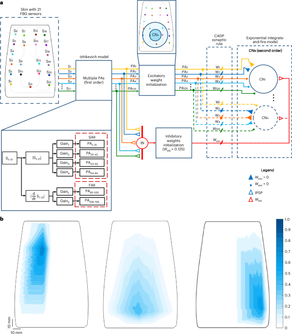
The objective of this work was to develop a biomimetic intelligent tactile device based on bioinspired e-skin and two-layered spiking neuronal network (SNN) to localize indentations applied onto the e-skin (Fig. 1a). To this end, we first fabricated a curved, soft e-skin embedding 21 FBGs, whose receptive fields were accessed to evaluate its intrinsic sensitivity (Fig. 1b). The wavelength variations of the sensors, collected via an automatized force-controlled indentation protocol (Methods), were then processed through a model consisting of two neuronal layers. The first layer is based on first-order neurons that mimic type II mechanoreceptors of the human skin. The spiking output of these neurons is then conveyed to the second network layer, inspired by the cuneate nucleus intracellular dynamics through 1,036 functionally organized secondary neurons (CNs) and interneurons (INs)18,29 (Methods). To evaluate the proposed model, trained via a synaptic learning protocol based on calcium-dependent synaptic plasticity29, and consistent with the assumption that the tactile information is spatially interpreted in the cuneate nucleus9, we estimated the location of indentations applied onto the e-skin from the spiking activity of the implemented secondary neurons. In addition, we assessed the model features through comparisons with biological systems.

a, Two-layer SNN for the localization of stimuli onto the e-skin. The first layer is composed of 126 PAs that mimic type II mechanoreceptors (SAII and FAII). These PAs make excitatory synapses with both CNs (coloured filled triangles and dots) and inhibitory INs (coloured empty triangles). The INs convey inhibitory postsynaptic potentials (IPSP) to the CNs (red, empty triangles). Both CNs and INs form the second layer of the network. The weights of the second-order neurons are trained through a calcium-dependent (CADP) synaptic rule. b, Large and overlapping receptive fields, with marked sensitive hotspots (dark blue), of three FBG sensors of the e-skin, mimicking type II PAs.
Receptive fields of e-skin FBG sensors mimic those of type II mechanoreceptors
The developed artificial skin embedded 21 FBG sensors in a polymeric substrate to smoothly transmit the applied external loads to the optical sensors. The distribution of the optical sensing units was inspired by that of human mechanoreceptors in the forearm, with a higher density near the wrist11,36,37. In addition, the FBGs in the silicone substrate were arranged to somehow resemble the functional role of type II mechanoreceptors. Located deep in the dermis, these receptors present large overlapping receptive fields with different sizes and sensitivities and smooth borders7,37. The characterization of e-skin sensitivity, through the normalization of the FBG wavelength variations in response to quasi-static indentations (Methods), demonstrated that the sensor receptive fields resemble those of type II mechanoreceptors, exhibiting large receptive fields with a single marked hotspot and sensitivity overlapping with the neighbouring transducers (Fig. 1b and Extended Data Fig. 1).
First-order neurons of SNN emulate type II PAs
Given the functional similarity of the FBGs to type II mechanoreceptors, the first neuronal layer of the SNN was conceived to emulate SAII and FAII PAs. Hence, each sensor output was multiplied by a matrix of gains (Extended Data Table 1) and fed as an input current to six first-order neurons, four SAIIs and two FAIIs, consistent with the biological ratio among the density of type II mechanoreceptor families36, totalling 126 PAs (Methods). This architecture enabled the translation of the FBG wavelength variations (Δλ; Fig. 2b) and their derivatives (Fig. 2c), which scale with the indentation stimulus (Fig. 2a), into spike responses, generated through the regular spiking Izhikevich’s neuron model (Fig. 2d)38. As the Ruffini endings encode skin stretches and show a sustained response to skin indentation2,39,40, the raw Δλ signals (Fig. 2b), encoding strains in the e-skin, were the inputs to the SAII model. The resulting firing rate was proportional to the applied load, which plateaus when stationary forces occur (Fig. 2e). The Δλ first temporal derivatives (Fig. 2c) were, instead, the sensory input to FAII afferents, since the Pacinian corpuscles encode transient tactile stimuli, that is, loading and unloading states (Fig. 2f)2,8. It is worth noticing that the behaviour of the SAII units (Fig. 2e) is valuable to decode contact intensity information, in line with biological hypotheses41. In particular, the more intense the applied force, the higher the firing rate of the slowly adapting mechanoreceptors (Fig. 2g and Supplementary Table 1). We also observed a discharge activity for high loads (greater than 3.5 N), as it happens in biological systems (Fig. 2g and Supplementary Table 1)42,43. As expected, we demonstrated that the average interspike intervals (ISIs) for each force range decrease with a higher intensity of the stimuli. The relationship between the logarithm of the ISI values and the logarithm of the percentage of the applied load is linear (Fig. 2h; Pearson correlation coefficient, ρ = 0.99; linear fitting polynomial: log[SAIIFiring Rate] = –0.38 Hz/N × log[Stimulus intensity, %] + 1.41 Hz; R2 = 0.98; average SAII firing rates and ISI in Supplementary Table 1), consistent with the results of the characterization of SAII units of the hairy skin of mammals, as it is that of the human forearm43. In addition, considering the dynamics of the mechanical indentations applied to the e-skin, the ISI range (approximately 50–100 ms) is consistent with neurophysiological findings43.

a, Stimulus applied onto the e-skin during an indentation. Force values are recorded by means of a load cell attached to the end-effector of the indenting robot. b, Response of the 21 FBG sensors. c, First derivative of the FBG sensor signals. d, Spiking activity of the modelled SAII and FAII grouped by gain (Gi) value. e, Firing rate of the active SAII of the SNN. f, Firing rate of the active FAII of the SNN. g, SAII firing rate distributions per force-level range (0.25–4.25 N, with a step of 0.5 N) for the dataset of 1,846 indentations. The median of each distribution is indicated by a solid green line within the box, whose black edges represent the first and third quartiles (values are reported in Supplementary Table 1); the whiskers extend to 1.5 times the IQR beyond the quartile boundaries. h, Relationship between stimulus intensity percentage and SAII ISI. The two parameters are expressed in the logarithmic scale.
Organization of second-order neurons of SNN resemble a plausible structure of cuneate nucleus
The second layer of the proposed SNN was designated to emulate the cuneate nucleus intracellular dynamics. It was composed of 1,036 functionally organized CNs and INs, each of the latter making an inhibitory synaptic connection with a CN (Fig. 1a). Biologically speaking, the CNs present complex receptive fields that, in general, are larger than that of PAs and comprise both excitatory and inhibitory subfields44. This enables sensitivity to specific spatial characteristics, allowing them to perform the spatial computation of tactile stimuli24,30,31. In addition, the cuneate nucleus has a functional somatotopic organization that may contribute to human tactile discrimination ability33,45,46. To provide our network model with these peculiar features, we defined the CN receptive fields, designed to include at least 12 PAs belonging to a specific region of the e-skin. Physiologically, convergent PAs with overlapping receptive fields, as it is in our system, determine larger secondary receptive fields44. Hence, each CN receives projections from the included PAs and these PAs could also establish connections with other secondary neurons, whose receptive field includes them. This connectivity entails that neighbour CNs have overlapping receptive fields, consistent with biological findings, according to which these overlaps are argued to implement input-feature segregation32. This approach generated a somatotopic map of the e-skin (Methods).
Excitatory and inhibitory synaptic learning of SNN second-order neurons
All the 126 PAs were provided to the 1,036 CNs as excitatory (wexc,i) and inhibitory (winh) synapses (Fig. 1a). The excitatory weights were initialized with the inverse of the Euclidean distance between the PAs and the functionally organized CNs within the receptive fields (Fig. 1a). Conversely, the weights of the mechanoreceptors outside the receptive field area were zeroed (Fig. 3a and Methods). The initial inhibitory weights winh were equal to 0.125 for all the implemented CNs29. A synaptic learning protocol based on calcium-dependent synaptic plasticity with a gradual synaptic weight transformation at each tactile stimulus presentation was performed (Methods). The post-learning excitatory synaptic weights and the evolution of the excitatory weights for one training fold are presented in Fig. 3b,c, respectively. The post-learning inhibitory synaptic weights are represented in Fig. 3d. It is worth noticing that the final winh values were close to 0 for all the CNs. This behaviour occurred because the update of winh values, which are responsible for regulating the firing rate of the CN calcium channels, was performed with a moving average of the firing rate of the last five indentation presentations, to avoid instability (Methods). Additionally, in the proposed SNN, most CNs should be silent depending on the site of the stimulus applied onto the e-skin, resulting in both low activity of the calcium channels and small winh. In general, the slowly adapting PAs had a greater potentiation (that is, increase) in their synaptic weights, especially in the case of SAIIs with higher firing activities (gains G3 and G4; Fig. 3b,c). The implemented synaptic learning rule potentiated the PA synapses that had high correlation with the CN total calcium activity. Therefore, the PA synapses with firing behaviour synchronized with the PAs having higher initial excitatory synaptic weights are more susceptible to potentiation of their synaptic weight18,29. This explains the substantial weight increase in SAIIs, given that the indentation task with plateaus (Fig. 2a) resulted in a higher firing rate for these afferents (Fig. 2d).

a, Initial excitatory weights generated from the CN receptive fields considering a heuristic rule. b, Final excitatory weights. c, Difference between the final and initial excitatory weights. d, Final inhibitory weights of the 1,036 CNs.
Spiking activity of SNN second-order neurons correlates with applied stimulus intensity
The spiking activity of 1,036 CNs was assessed for each indentation sample. The intensity of the firing of the CNs (Fig. 4b) was found to be qualitatively related to the force applied to the e-skin (Fig. 4a) during the indentations. The somatotopic maps in Fig. 4c show the spatial cumulative activations of the CNs during 1 s for two different loading conditions, that is, the first (~0.4 N) and the second (~2.3 N) level of the indentation force profile (Fig. 4a), respectively. It can be observed that the active area enlarges for higher stimulus intensities, with greater spiking activities inside the receptive field of the stimulated CN (Fig. 4c). This behaviour was also quantitatively demonstrated by grouping the CN responses of the whole indentation dataset by the force level, resulting in median numbers of active CNs of 329 (interquartile range (IQR) = [116, 450.75]) and 545 (IQR = [481, 685]) for the first and second force levels, respectively (Fig. 4d), with significant differences between the two loading conditions (Mann–Whitney U-test, P value = 0). In addition, as the applied load increases, the CN spiking activity intensifies with a monotonic increasing trend, consistent with the findings of studies on mammals (Extended Data Fig. 2 and Supplementary Table 2)47. In line with physiology, the modelled CNs presented bursting behaviours, reaching instantaneous spiking frequencies of nearly 1 kHz, where the increasing firing rate was supposed to encode the intensity of the stimulus24,32,48,49. In conclusion, it can be argued that both CN spatial activation on the modelled somatotopic map, provided by progressively recruiting PAs as the contact area increases32, and their spiking firing rates encode the intensity of the applied stimulus, consistent with neurophysiological findings on touch encoding50.

a, Indentation force profile presenting stimulus plateaus (force level 1, ~0.4 N; force level 2, ~2.3 N). b, Spiking activity of the 1,036 CNs of the SNN second layer. c, Somatotopic maps of the CN activations (cumulative spike numbers over 1 s of stimulus) for the two force levels of the sample indentation in a. d, Distributions of the number of active CNs at the two force levels for 1,655 indentations. The median is indicated by a solid line within the box, whose edges represent the first and third quartiles; the whiskers extend to 1.5 times the IQR beyond the quartile boundaries.
SNN enables indentation localization with biologically plausible temporal resolution
To evaluate the two-layer SNN, we estimated the indentation location by computing the weighted average of all the CN spikes and the centroids of the spiking neurons over the e-skin somatotopic map (Methods). Figure 5 illustrates the neural activity of the CNs organized in the e-skin somatotopic map, the estimated locations weighted by the neural activity of the second-order neurons (weighted location) and the actual indentation site, for some indentations applied to different e-skin regions. We also report simulations of the real-time response of the model in terms of the weighted location estimation within a moving window (Supplementary Videos 1 and 2), evidencing its generalization capability.

For each sample indentation, the CN somatotopic map with neuron activations (left) and target and estimated location of the stimulus on the e-skin and error d, that is, Euclidean distance, between them (right) are shown.
We then calculated the location prediction error as the Euclidean distance between the weighted and target stimulus sites for all the indentation test points (Fig. 6a). The fourfold cross-validation resulted in a median location prediction error of 36.26 mm (IQR = [20.46 mm, 52.14 mm]) and 14.11 mm (IQR = [7.47 mm, 28.56 mm]) before and after the learning process, respectively (Supplementary Table 3 and Fig. 6b,c). Our results and the consistency of the prediction error achieved across the four folds (Supplementary Table 3) show that the proposed model is robust and has a high learning capability. In addition, we estimated contact positions through a simpler approach involving the calculation of the weighted average of the FBG Δλ (Methods). This resulted in a median error of 15.72 mm (IQR = [9.40 mm, 28.82 mm]) for the whole e-skin surface (Extended Data Fig. 3 shows a few prediction examples). The prediction errors of the different approaches for different regions of interest (ROIs) are represented in Fig. 6c (error values are listed in Supplementary Table 4). In general, this analysis resulted in larger localization errors at the edges of the e-skin. Conversely, the e-skin central region (ROI radius ≤ 45 mm), that is, the area with a higher density of sensors and in which the receptive fields of the CNs entirely map onto the e-skin surface, showed a median prediction error smaller than 10 mm for the SNN approach (Fig. 6b,c). In the same region, the estimation of the contact position through the weighted average of the FBG signals resulted, instead, in larger median errors and higher variability (Fig. 6c and Supplementary Table 4). These results demonstrate the effectiveness of the SNN approach for stimulus localization and its consistency with neurophysiological findings about the forearm tactile acuity (10–18 mm)51,52. Then, we investigated the temporal resolution of the developed spiking architecture for stimulus localization. After 10 ms from the onset of contact, the neuronal network was able to reach a median localization error of 14.36 mm (IQR = [8.17 mm, 25.24 mm]), which is similar to that achieved when considering longer time windows, such as 2 s (14.05 mm, IQR = [7.45 mm, 28.70 mm], Mann–Whitney U-test, P value = 0.51; Extended Data Fig. 4). These outcomes are consistent with some neurophysiological hypotheses on the dispersion of the latency (~14–28 ms) of stimulus transmission from the hand mechanoreceptors to the cuneate nucleus9.

a, Test indentation points of the fourfold cross-validation randomly distributed over the e-skin. b, Prediction error, that is, Euclidean distance, of the contact location over the e-skin area. c, Median and IQR values of the prediction errors of the SNN before and after synaptic learning, and the FBG weighted average for different ROI radii. d, Topographic latency map for one contact point in the two-point discrimination analysis. e, Topographic latency map for two contact points in the two-point discrimination analysis. f, Piecewise sigmoid fitting of the two-point detection rate as a function of the distance between the two probes used in the Weber two-point discrimination test. The two-point discrimination threshold (th) of the e-skin is reported, too.
SNN generalizability enables two-point discrimination
To demonstrate the generalization features of the SNN in localizing tactile stimuli onto the e-skin, the Weber two-point discrimination test was conducted using custom probes with tips at distances ranging from 0 mm to 60 mm (Supplementary Video 3). The analysis of the latency of the CN spiking responses resulted in a topographic map in which the minima were searched and identified as contact points. The latency maps for a single point and a 50-mm two-point indentation trial are represented in Fig. 6d,e, respectively. The minimum identifiable distance between the points was the CN receptive field radius44. The detection rates for each probe distance were computed (Supplementary Table 5) and a piecewise logistic curve was fitted to the data to determine the psychometric relationship (Fig. 6f; parameters a = 0.53, b = 0.35 mm−1, c = 35.26 mm and d = 0.27; Methods). The two-point discrimination threshold, that is, the probe distance value corresponding to a psychometric probability of 0.75, yielded 42.25 mm, consistent with neurophysiological findings on the discrimination of pairs of contacts on the human forearm (~30–45 mm)53,54.
Discussion
This study investigated how a bioinspired SNN can decode tactile stimuli applied onto a biomimetic large-area e-skin, embedding FBG transducers in a soft polymeric substrate, starting from the hypothesis that the first stage of spatiotemporal decoding of tactile information occurs at the cuneate nucleus32. We attempted to functionally emulate the first- and second-order neurons of the somatosensory system, to further achieve its computational and learning efficiency. To this aim, we first developed a forearm-shaped e-skin, whose sensor arrangement and receptive fields were intended to morphologically mimic type II mechanoreceptors of the human skin (Fig. 1b)7,11,36,37. Physiologically, the human arm has a tactile innervation density of 12 units cm−2 (ref. 36), which results in approximately 1,800 PA innervation distributed over an area of 150 cm2 (the approximate e-skin area), with hundreds of PAs sending projections onto a single CN9. Considering this, the artificial morphological reproduction of the tactile decoding channels is still a challenge, given the current technological limitations of most sensing systems that prevent the development of extremely sensor-dense devices4,18,21,55. Our approach benefited from the high integrability and multiplexing of FBG sensors and leveraged on the modelling of six sensory afferents per FBG. Through the proposed calibration of the Izhikevich model of regular spiking neurons38,56,57,58,59, the resulting 126 PAs recreated a variety of firing dynamics, mimicking fast and slowly adapting mechanoreceptors, whose activity encoded stimulus transients and intensities, respectively (Fig. 2)7,8,43. The modelled PAs sent projections onto the 1,036 CNs and INs of the SNN second layer, emulating the biological connectivity of the cuneate nucleus (Fig. 1a). Inspired by physiology, the CNs were designed to have large overlapping receptive fields, thereby realizing a somatotopic map of the e-skin. This spatial organization in combination with the unsupervised learning rule, based on the CN intracellular dynamics and a heuristic initialization of the synaptic excitatory weights (Fig. 3), were paramount for the localization of tactile stimuli through the spiking activity of the secondary neurons18,29,32,44. Our SNN model was proven to be effective in estimating the indentation location under varying conditions of force and position (Fig. 5), with a median error of about 14 mm and less than 10 mm in the central region of the e-skin (Fig. 6b,c). Physiologically, the human ability of stimulus localization and tactile acuity are enhanced in body regions with a higher density of mechanoreceptors, such as the fingers36,60. Despite the low density of sensors in the e-skin, our SNN allowed to reach results consistent with neurophysiological findings51,52, with median errors and variability lower than those directly obtained from the FBG signals on the considered ROIs through a non-bioinspired approach (Fig. 6c and Supplementary Table 4). Additionally, our model intrinsically enabled discrimination between two contact points without any further training, an outcome that was enabled by the implemented bioinspired learning paradigm, confirming the generalization properties of our SNN. The model two-point discrimination threshold of about 42 mm aligns with that of the human forearm53,54 and conforms to the theory of convergence of PAs with broad receptive fields44 (Fig. 6f). The stimulus localization on the e-skin was enabled by both CN topographic organization and firing activity (Fig. 5 and Extended Data Fig. 4). Spatiotemporal coding strategies were also observed in regions of the somatosensory cortex61 and hypothesized to occur even at the cuneate-nucleus level9. We also observed that the spiking activity of the CNs, as well as the extension of the active area on the e-skin, is correlated with the intensity of the applied stimulus (Fig. 4 and Extended Data Fig. 2), in line with evidence on mammals47 and with the hypotheses that input-feature segregation may occur in the cuneate nucleus24,32,48,49.
This study, thus, demonstrates that the bioinspired design of both e-skin and two-layered SNN, supported by biological findings, enabled the unsupervised learning of skin-contact localization over large areas with the feasibility of generalization to more complex stimuli. This outcome can offer both technological and scientific applicability.
First, this achievement supports the perspective of transferring our approach to real-world applications, such as bionics and robotics. Tactile feedback could be provided to persons with disabilities, such as prosthesis users or quadriplegic subjects, by means of either invasive intraneural or intracortical stimulation or non-invasive wearable interfaces62. The restoration of the disrupted sensory pathways should elicit natural sensations, for which intuitive and biomimetic feedback is required63,64. Although our bioinspired e-skin holds a huge potential for integration in bionic devices, given its mechanical conformability and its robustness to unstructured setting interferences, the bulkiness of the optoelectronic interrogator prevented its applicability in real sensory restoration architectures so far. However, the recent advancements of miniaturized photonics will boost the deployment of FBG-based e-skin in bionics, promising major breakthroughs in the near future65,66.
Considering the robotics scenarios of Industry 4.0 and 5.0, the implementation of biomimetic intelligence, in combination with large-area e-skins on machines, is essential for safe interactions with the surroundings4,11,13,67. The new generation of robots should autonomously navigate and operate in unstructured environments and cooperate with humans in various workspaces, ranging from industrial production to medical and rehabilitation care11,68,69,70. For most applications, collaborative machines require a spatial resolution of 10–40 mm (ref. 71), which is consistent with the performance of our system. The artificial emulation of the natural tactile sensory pathways in robots could foster human-like responsiveness and enable more efficient computations and hardware resource usage, as that in biological systems13. In addition, biomimetic e-skins are promising for the integration of non-invasive sensory feedback interfaces, which could enhance safety and collaborative tasks in the telepresence and teleoperation frameworks72. In these scenarios, where intuitiveness and efficiency are required73, our system entails a huge potential for real-time deployment, given its architecture based on event-driven processing. Online implementation of soft neuromorphic models has been demonstrated to be feasible via the Euler method, selecting the discretization timing in the millisecond scale to guarantee the convergence of artificial neurons firing in the order of tens of hertz typical of the human somatosensory system, in a trade-off between the overall accuracy and convergence and the computational burden74. In addition, the ongoing advancements of neuromorphic hardware solutions hold promise to surpass the powerful, but costly, conventional electronics of deep learning accelerators13,75. Future works will target the on-chip deployment of our SNN, aiming at parallel energy-efficient hardware architectural processing instead of algorithmic implementations.
Regarding the contribution to neuroscientific research, in this work, we provided modelling evidence supporting, to some extent, the plausible hypothesis that the cuneate nucleus is the first stage of tactile information interpretation, through overlapping receptive fields and the capacity to convert spatiotemporal spiking codes of the PAs into spatiotemporal features and functionalities, tasks previously attributed mainly to the somatosensory cortex31,32,34,76. Nevertheless, the functional role of the cuneate nucleus in somatosensory processing is not yet fully understood, due to the complexity of performing intracellular recordings in this structure77,78. Our model, as an open-access neurocomputational machine intelligence tool79, can serve as an engineering enabler for the investigation of second-order neuron functions. It offers tools to evaluate the functional effect of neuronal architectures applied to electrophysiological recordings that may be available in future investigations of the somatosensory system, with particular reference to the encoding of stimulus intensity and localization by second-order neurons.
Methods
Sensitive FBG-based e-skin
The experimented e-skin (Extended Data Fig. 5) had size and shape similar to those of the human forearm. To mimic biomechanical compliance, a soft silicone polymer (Dragon Skin 10 medium, Smooth-On) was used to realize a flexible patch to embed an optical fibre with 21 FBG sensors. It was fabricated by a three-step process11: (1) a first silicone pouring in a custom mould to obtain a bottom layer with a groove; (2) the embedding of the fibre along the grooved path; (3) a second silicone pouring to cover the fibre itself and provide robustness to the patch. The e-skin was then attached to a custom three-dimensionally printed plastic support to guarantee stability. The optically sensitive elements were FBGs (length, 10 mm) distributed along the designed path running throughout the e-skin resemble the sensitivity features of the human forearm, that is, with an increasing density from the proximal to distal parts. These gratings are interference patterns inscribed within the core of a single optical fibre. When broadband spectrum light, sent by means of an optoelectronic interrogator, passes through the fibre cable and hits an FBG, it is partly back-reflected to the input point, as a spectral peak centred at a characteristic wavelength, λB:
$${\lambda }_{\rm{B}}=2 {n}_{{{\rm{eff}}}}\varLambda,$$
(1)
where neff is the effective refractive index of the optical fibre and Λ is the pitch of the specific grating80. The λB value of the e-skin FBGs were, hence, defined by fabrication and ranged between 1,520 nm and 1,580 nm with a step of 3 nm. Wavelength shifts occur when a deformation is applied to the sensor11, thereby allowing the encoding of tactile stimuli. Considering this feature and to reduce the effects of potential prestrains that could have impacted the residual deformability of the sensors in response to external tactile stimuli, the FBGs were arranged on straight fibre segments.
Indentation data collection
The training and validation of the proposed model required the collection of a dataset of indentations applied over the e-skin surface. For this purpose, an automatized indentation protocol was executed, with 1,846 target points to touch, computed as the centroids of the triangles of a random mesh of the skin surface. A bimanual robotic platform, consisting of two anthropomorphic arms (Racer-5-0.80, Comau), was programmed to cooperate during the indentation protocol (Extended Data Fig. 5): one robot performed the tactile tasks, whereas the other held and oriented the e-skin. The indenting robot reached each target site perpendicularly, touching the skin with a spring-like hemispherical probe attached to the end-effector. Force feedback measured by means of a load cell (Nano 43, ATI Industrial Automation), mounted at the base of the indenter, was provided to control the robot to release the contact when exceeding a threshold (2.5 N) and then fly to a new target point. The control code consisted of dedicated routines (LabVIEW, National Instruments) running on both an industrial controller (IC-3173, National Instruments), to send commands to the robots, and a PC, for managing and checking the experiments. During the indentation sessions, force and FBG signals, the latter read by means of an optical interrogator (FBG Scan 904, FBGS Technologies), were collected at a 100-Hz rate, and saved into text files together with the Cartesian coordinates of the contact sites.
Assessment of receptive fields of e-skin FBG sensors
The receptive fields of the FBG sensors populating the skin were represented as two-dimensional contour maps depicting the spatial distribution of sensitivity to contact force. Hotspot regions in dark blue indicate the maximum sensitivity (Fig. 1b and Extended Data Fig. 1). To obtain the FBG receptive fields, the wavelength variation signals (Δλ) from each FBG sensor were averaged over 500 ms captured on the highest force plateau, that is, the second force level, and divided by its average value. The obtained results were then normalized with respect to the highest FBG sensitivity value, to have sensitivity maps ranging from 0 to 1. This procedure was performed using all the available indentation samples.
First-order neurons: type II PA model
The 21 FBG signals were the input of the PA models. Each sensor signal was resampled at a frequency of 1 kHz to establish a regular firing dynamics consistent with the discretization of the Izhikevich neuronal model74. The FBG signal derivatives were computed to obtain the dynamic components of the indentations, that is, the loading and unloading phases of the varying force levels applied to the e-skin. The absolute values of both raw and differentiated signals were calculated to feed the Izhikevich neurons as input current I, to mimic the adaptation dynamics and firing response of type II mechanoreceptors, that is, Ruffini endings (SAII) and Pacini corpuscles (FAII)38. To simulate the physiology of type II PAs in terms of the ratio between slowly and fast-adapting units, that is, two SAIIs to one FAII36, their diverse sensitivity and the different-sized overlapping receptive fields, the raw absolute FBG signals and their derivatives were multiplied by four and two distinct gains. Hence, six mechanoreceptor models were considered for each FBG sensor (Fig. 2), resulting in 126 input currents for the first-order neuron models. Extended Data Table 1 shows the gains used for the SAII and FAII models. The SAII gains were selected through some pilot tests and empirical analyses, where we assessed whether the increase in gain was generating an increase in the firing rate within the physiological range documented in the literature43. Specifically, the average ISIs (that is, the inverse of the average firing rates) corresponding to each force range were computed, and their logarithmic values were fitted to the logarithm of the stimulus intensity percentage (force values normalized by the maximum of 4 N; Fig. 2h). The results were then compared with background neurophysiological findings43, particularly to the ISI characterization of SAII units. The FAII gains were selected following the same empirical approach, that is, by evaluating the spiking activity at load transients. It is worth noticing that a general procedure for establishing the gains of the input currents of the Izhikevich model for artificial mechanoreceptor simulation has not yet been established in the literature. Thus, several studies, such as ref. 58, reported this empirical method of gain selection according to the specific application.
The Izhikevich model consists of a system of differential equations that can be solved via the Euler method74. Equation (2) describes the dynamics of the membrane potential v of the neuron; equation (3) represents the recovery variable u, responsible for the repolarization of the neural membrane; equation (4) describes the membrane potential restoration and the recovery variable update when v reaches the 30-mV firing threshold:
$$\frac{{{\rm{d}}v}}{{{\rm{d}}t}}=A{v}^{2}+{Bv}+C-u+{{{\rm{Gain}}}}_{n}\frac{I\left(t\right)}{{C}_{{\rm{m}}}},$$
(2)
$$\frac{{{\rm{d}}u}}{{{\rm{d}}t}}=a\left({bv}-u\right),$$
(3)
$${\rm{If}}\,v\ge 30\,{{\rm{mV}}},{\rm{then}}\left\{\begin{array}{c}v\leftarrow c\\ u\leftarrow u+d\end{array}\right.,$$
(4)
where A, B, and C are standard variables of the Izhikevich model; t represents time; a is the timescale of u; b is the sensitivity of u to the membrane potential; c is the membrane resting potential value; and d modulates the dynamics of the after-spike reset of the recovery variable u. For the implemented mechanoreceptors, we choose the parameters Gainn (Extended Data Table 1) that reproduced a regular firing behaviour.
Encoding of contact intensity by SNN PAs
The activity of type II mechanoreceptors was analysed to investigate relationships with the intensity of the applied load. For this purpose, the perpendicular force profile was extracted for all the 1,846 indentations. For each indentation, SAII and FAII units were considered separately. First, their corresponding firing rates were calculated on moving time windows of 100 ms, with an overlap of 50 ms. For each window, the firing rate was extracted as follows:
$${{{\rm{FR}}}}_{X}=\frac{{N}_{{{\rm{spikesX}}}}}{{w}_{{{{\rm{t}}}}} {N}_{{{\rm{neuronXactive}}}}},$$
where the subscript X indicates the type of mechanoreceptor (SAII or FAII), wt is the duration of the time window, NspikesX is the number of spikes of the X units in wt and NneuronXactive is the number of active neurons of each type in the selected window. The resulting firing rates were compared with the corresponding force profile (Fig. 2a–f). Then, the SAII firing rates were grouped for force levels, ranging from 0 to 4 N, with a step of 0.5 N. The corresponding distributions were analysed and the relevant statistics computed (median values and first and third quartiles; Fig. 2g and Supplementary Table 1). For each load-intensity level, the mean SAII firing rate value was extracted to further derive the relationship with the applied loads. For that, the linear Pearson correlation coefficient ρ was calculated. Then, the first-order polynomial that fitted the logarithm of the SAII average firing rates to the logarithm of the percentage of the applied load, normalized by 4 N, was extrapolated. The R2 coefficient was computed to assess the goodness of the linear fit (Fig. 2h).
Second-order neurons: CN model
The second layer of the SNN was composed of 1,036 CNs, modelled with the mathematical implementation based on the exponential integrate-and-fire approach29. This model reproduces the complete dynamics of the membrane potential of CNs, as described in equation (5), along with a detailed modelling of the activity of low-threshold voltage-gated calcium channels and calcium-activated potassium channels:
$${C}_{{\rm{m}}}\frac{{{{\rm{d}}V}}_{{\rm{m}}}}{{{\rm{d}}t}}={I}_{{\rm{L}}}+{I}_{{{\rm{spike}}}}+{I}_{{{\rm{ion}}}}+{I}_{{{\rm{ext}}}}+{I}_{{{\rm{syn}}}}.$$
(5)
In equation (5), Cm is the capacitance of the neural membrane; Vm is the CN membrane potential; IL is the leak current of the neuron (equation (6)); Ispike is the spike current that recreates the action potential onset and the fast neuron depolarization (equation (7)); Iion is the ionic current resulting from the summation of the currents of voltage-gated calcium channels (ICa) and calcium-activated potassium channels (IK; equation (8)); Iext is the external current that can be injected into the neuron (in this study, it is equal to 0); and Isyn is the synaptic current (equation (9)), where each synapse (i) is activated by a PA.
$${I}_{{\rm{L}}}={-\bar{g}}_{{\rm{L}}}\left({V}_{{\rm{m}}}-{E}_{{\rm{L}}}\right),$$
(6)
$${I}_{{{\rm{spike}}}}={\bar{g}}_{{\rm{L}}{\rm{L}}}{\Delta}_{{\rm{t}}}\exp \left(\frac{{V}_{{\rm{m}}}-{V}_{{\rm{t}}}}{{\Delta }_{{\rm{t}}}}\right),$$
(7)
$${I}_{{{\rm{ion}}}}={I}_{{{\rm{Ca}}}}+{I}_{{\rm{K}}},$$
(8)
$$\begin{array}{l}{I}_{{{\rm{syn}}}}={g}_{\max }\sum _{i}{w}_{{{\rm{exc}}},i}\exp \left(-\tau \left(t-{t}^{* }\right)\right)\left({E}_{{{\rm{rev}}},{{\rm{exc}}}}-{V}_{{\rm{m}}}\right)\\\qquad\;\;+\,{g}_{\max }{w}_{{{\rm{inh}}}}\sum _{i}\exp \left(-\tau \left(t-{t}^{* }\right)\right)\left({E}_{{{\rm{rev}}},{{\rm{inh}}}}-{V}_{{\rm{m}}}\right),\end{array}$$
(9)
where wexc,i is the excitatory synaptic weight; t* is the time at which a spike occurs and winh is the inhibitory synaptic weight. Isyn can be, hence, expressed as the sum of the excitatory and inhibitory synaptic currents of all the synapses of the individual PAs. The definitions of the other variables and their respective values are reported in Supplementary Table 6.
The current ICa is described by equation (10) and the current IK, by equation (11):
$${I}_{{{\rm{Ca}}}}=-{\bar{g}}_{{{\rm{Ca}}}}{x}_{{{\rm{Ca}}},{a}}^{3}{x}_{{{\rm{Ca}}},i}\left({V}_{{\rm{m}}}-{E}_{{{\rm{Ca}}}}\right),$$
(10)
$${I}_{{\rm{K}}}=-{\bar{g}}_{{\rm{K}}}{x}_{{{\rm{K}}}_{{{\rm{Ca}}}}}^{4}{x}_{{{\rm{K}}}_{{{\rm{V}}_{\rm{m}},}}}^{4}\left({V}_{{\rm{m}}}-{E}_{{\rm{K}}}\right),$$
(11)
where \({\bar{g}}_{{{\rm{Ca}}}}\) and \({\bar{g}}_{{\rm{K}}}\) are the maximum conductance; ECa and EK are the action potentials of the calcium and potassium channels, respectively; and xCa,a, xCa,i, \({x}_{{{\rm{K}}}_{{{\rm{Ca}}}}}\) and \({x}_{{{\rm{K}}}_{{{\rm{V}}_{\rm{m}}}}}\) are the activity states of the channels. These values are provided in Supplementary Table 6.
In this model, both ion channels (xCa,a and xCa,i) are considered as sources of the membrane calcium concentration of the CN ([Ca2+]). Thus, we proposed that the activity of the total neuron calcium concentration follows equation (12).
$$\begin{array}{l}\frac{{\rm{d}}\left(\left[{{{\rm{Ca}}}}^{2+}\right]\right)}{{{\rm{d}}t}}={{\rm{BCa}}}\bar{g}{C}_{a}{x}_{{{\rm{Ca}}}{,a}}^{3}x{C}_{a,i}\left({V}_{{\rm{m}}}-{E}_{{{\rm{Ca}}}}\right)\\\qquad\qquad\;+\,\left(\left[{{{\rm{Ca}}}}^{2+}\right]_{{{\rm{rest}}}}-\left[{{{\rm{Ca}}}}^{2+}\right]\right)/{\tau }_{\left[{{{\rm{Ca}}}}^{2+}\right]}.\end{array}$$
(12)
The relevant parameters are reported in Supplementary Table 2.
Functional organization of SNN second-order neurons to model a somatotopic map of the e-skin
To functionally mimic the organization of the cuneate nucleus, we generated an e-skin grid mesh with 29 × 38 edges, that is, 28 × 37 subregions. In this mesh, each subregion represented a CN, and its centroid represented the centre of its receptive field. In total, 1,036 CNs were created with circular overlapping receptive fields of 41.67-mm radius each. The criterion for the definition of the size of the CN receptive field was to include at least two FBG sensors in the corresponding sensitive area of the e-skin and, thus, 12 PAs, consistent with the number of dominant PAs that project into a CN found in neurophysiological studies on mammals and simulations of human tactile perception24. This approach allowed us to determine a CN somatotopic map of the e-skin.
Connectivity of SNN and initialization of synaptic weights
In our model, each of the 1,036 CNs was fully connected to the 126 PAs, with excitatory weights ranging from 0 to 1, and to a single inhibitory synapse (Fig. 1a, red triangle), with an IN that grouped the responses of all the 126 PA projections (Fig. 1a, coloured empty triangles). This connectivity enabled the potentiation or depression of all the synaptic weights during the learning process. In this model, the magnitude of the postsynaptic potential projected into a CN for a given sensory input is dependent on both excitatory (wexc,i) and inhibitory (winh) weights, as described in equation (9)18,29. The presynaptic excitatory weights were initialized as the inverse of the Euclidean distances between the position of the 21 FBG sensors in the skin and the 1,036 centroids of the CNs. Then, the obtained values were rescaled between 0.2 and 1. The initial excitatory weights (wexc) of the PAs corresponding to the sensors outside the area of the CN receptive fields were instead set to 0 (Fig. 1a, coloured dots). In this way, only the mechanoreceptors inside the CN receptive field region had initial weights greater than 0 (Fig. 1a, coloured filled triangles). All the inhibitory synaptic weights (winh) were instead initialized to 0.125.
Synaptic learning protocol of SNN second-order neurons
Inspired by calcium-dependent synaptic plasticity, we implemented a synaptic learning process29, where the total inhibitory weights (winh) and presynaptic excitatory weights (wexc,i) were updated at each stimulus presentation. According to our model, the excitatory weight potentiation of the presynaptic neurons (PAs) occurred when the total calcium activity (\({A}_{{{\rm{Tot}}}}^{{{{\rm{Ca}}}}^{2+}}\)) of the CN, as in equation (13), was strongly correlated with the local calcium activity (\({A}_{{{\rm{Loc}}}_{i}}^{{{{\rm{Ca}}}}^{2+}}\)) of a synapse (PA with the secondary neuron; equation (14)); otherwise, this synapse was depressed:
$${A}_{\rm{Tot}}^{{\rm{Ca}}^{2+}}={k}_{{{\rm{act}}}} \times [{{\rm{Ca}}}^{2+}],$$
(13)
$${A}_{\rm{Lo}{c}_{i}}^{{\rm{Ca}}^{2+}}=\frac{{\tau }_{1}}{{\tau }_{{\rm{d}}}-{\tau }_{{\rm{r}}}}\left[\exp \left(-\frac{t-{\tau }_{{\rm{l}}}-{t}^{* }}{{\tau }_{{\rm{d}}}}\right)-\exp \left(-\frac{t-{\tau }_{{\rm{l}}}-{t}^{* }}{{\tau }_{{\rm{r}}}}\right)\right],$$
(14)
where \({A}_{{Tot}}^{{{Ca}}^{2+}}\) is the total calcium activity of the CN; kact = 1 is an arbitrary constant; \({A}_{\rm{Loc}_{i}}^{{\rm{Ca}}^{2+}}\) is the local calcium activity due to a synapse i; τr = 4 ms is the rise time; τd = 12.5 ms is the decay time; τl = 0 ms is the latency time; τl = 21 ms is a constant to calculate the ratio; and t* is the time at which a PA spike occurs. To reach supralinearity in the local calcium activity, we used an approximative approach of subtracting an offset, that is, the 75% of the single-pulse activation peak activity, from the local calcium signal, and this resulting value was used as the local calcium activity (\({A}_{{{\rm{Loc}}}}^{{{{\rm{Ca}}}}^{2+}}\)), as proposed in ref. 29.
In the model, the individual excitatory weights actualization occurred during the presentation of each stimulus during the learning phase, and it is described as the integral of the correlation between local calcium activity (\({A}_{\rm{Loc}}^{{\rm{Ca}}^{2+}}\)) and total calcium activity (\({A}_{\rm{Tot}}^{{\rm{Ca}}^{2+}}\)), following equation (15):
$${\Delta w}_{{{\rm{exc}}},i}={\int}_{{\!t}_{0}}^{{t}_{\max }}\left\{\left({A}_{{Tot}}^{{\rm{Ca}}^{2+}}\left(t\right)-\left({{{\rm{Avg}}}}_{{A}_{{{\rm{tot}}}}^{{{{\rm{Ca}}}}^{2+}}}\times{{{\rm{Syn}}}}_{{{\rm{EQ}}}}\right)\right)\times{A}_{\rm{Loc}}^{{\rm{Ca}}^{2+}}\left(t\right)\right\}\times {\rm{K}}\times {{\rm{d}}t},$$
(15)
where \({{{\rm{Avg}}}}_{{A}_{{\mathrm{tot}}}^{{{\mathrm{Ca}}}^{2+}}}\) is the average of the last three values of the total calcium activity; SynEQ is the synaptic equilibrium defined as a linear function of the total excitatory synaptic weight with a dual slope having point 0 in 10 (decay = 0.04, if ∑wexc < SynEQ; decay = 0.12, if ∑wexc > SynEQ); and K is a constant gain factor defined by the sigmoid function represented in equation (16), with a gain step on the slope of 0.005.
$$S\left(t\right)=\frac{1}{1+{{\rm{e}}}^{-t}}$$
(16)
To avoid instabilities in synaptic learning, it was necessary to average the calcium activity; thus, the learning threshold was obtained by multiplying the average of the total calcium activity \({{\rm{Avg}}}_{{A}_{{\mathrm{tot}}}^{{{\mathrm{Ca}}}^{2+}}}\) by the synaptic equilibrium SynEQ.
Although the inhibitory synaptic learning is based on the firing rate of the CN calcium channels, winh, initially set to 0.125, is responsible for regulating the total activity of the calcium channels in the CN. Thus, the low activity of calcium channels was counteracted with a decrease in winh, and vice versa. For the model implemented in this work, winh was used to maintain the firing frequency of the calcium channels at a predefined set point of 20 Hz, and the update of winh was given by a dual-slope function zeroing at this set point. The synaptic learning protocol is summarized in a pseudo-code in the Supplementary Text.
The synaptic learning process was evaluated through a fourfold validation, such that for each training fold, 1,385 indentation samples were shuffled and presented to the model, thereby totalling 1,385 training cycles. In this step, only 1 s of data was used, including the beginning of the second indentation step (that is, the highest force level for each indentation). These data were the spikes (binary vector) of the first neuronal layer of mechanoreceptors (PAs). All the synaptic learning processes were separately performed for each of the 1,036 CNs.
Data post-processing and SNN performance evaluation
After the synaptic learning, the spike responses of 1,036 CNs were calculated for the indentations of each validation fold and processed to derive the stimulus intensity and location information.
Decoding of stimulus intensity through spiking activity of SNN second-order neurons
To demonstrate the increase in CN spiking activity when progressively higher loads were applied, the cumulative spike numbers inside the receptive field of the stimulated CN were computed for different loading conditions (Extended Data Fig. 2). To this aim, we evaluated the CN spikes in a 1-s window at the beginning of each of the two plateaus of the indentation force profile. In addition, the spatial activations of the CNs for the different force levels were explored. In this regard, the number of active CNs was calculated for the two load conditions and 1,655 of the applied indentations (Fig. 4d). A Mann–Whitney U-test test with a 0.05 significance level was performed to investigate whether the spatially distributed responses of the CNs could encode information on different intensities of the applied tactile stimuli.
SNN performance and temporal resolution for localization of stimuli on the e-skin
Regarding the prediction of the contact position, the spikes of the CNs were first summed over the indentation duration window. The sum of each neuron spike (Nspki) was then used for the weighted location estimation, as described in equation (17).
$${{{\rm{WL}}}}_{x,y}=\frac{{\sum}_{i=1}^{1,036}{{N}_{i}{{\rm{Loc}}}}_{x,y}\times{{{\rm{Nspk}}}}_{i}}{\mathop{\sum}\nolimits_{i=1}^{1,036}{{{\rm{Nspk}}}}_{i}},$$
(17)
where WLx,y is the location estimation in the skin x–y plane (considering the two-dimensional projection of the e-skin surface) weighted by the neural activation of the CNs (weighted position); Nspki is the number of spikes of a neuron in a time window; i is the CN ID (from 1 to 1,036); and NiLocx,y is the position of the centroid of a second-order neuron in the x–y plane of the modelled functionally organized cuneate nucleus. We estimated the weighted location on a 1-s sliding window with an overlap of 100 ms. To evaluate the location prediction error, we calculated the Euclidean distance between the real position of the indentation on the e-skin and the estimated weighted location (Fig. 5).
In addition, we compared the localization performance of the SNN with those achieved through the weighted average of the 21 FBG sensor wavelengths (FBG WLx,y), calculated as follows:
$${{\rm{FBG}}}{{{\rm{WL}}}}_{x,y}=\frac{{\sum}_{i=1}^{21}|{\Delta \lambda }_{i}|\times{({x}_{{{\rm{FBG}}}},{y}_{{{\rm{FBG}}}})}_{i}}{\mathop{\sum}\nolimits_{i=1}^{21}|{\Delta \lambda }_{i}|},$$
where Δλi and (xFBG, yFBG)i are the wavelength variation and two-dimensional coordinates of the ith FBG sensor, respectively. The FBG-based weighted average was computed for each timestamp of the corresponding non-zero force values. Then, the average location and Euclidean distance were calculated to obtain a single estimation and a single error value per indentation of the test sets of the four folds (Extended Data Fig. 3). The performance of both neuronal network and FBG weighted average in localizing the test stimuli were also assessed considering ROIs of different sizes. Starting from the centre of the skin, circular areas with an increasing radius-delimited (from 20 mm to 55 mm) portions of the e-skin surface were used to compute the contact estimation error, considering that all the test indentations fell inside the circular region. Median and IQR error values were calculated for each region size, grouping the results of the four cross-validation folds (Fig. 6c and Supplementary Table 4).
We then evaluated the temporal resolution of our system to localize the applied indentations. Specifically, considering that the sensors of the e-skin tracked the dynamics of the applied loading and unloading transients (Fig. 2a–c), we estimated the minimum amount of time needed by the trained SNN to reach its best localization performance. This approach aimed at investigating the stimulus conduction time from the simulated forearm mechanoreceptors, that is, the FBG sensors, to the modelled CNs, designated to localize contacts onto the e-skin. We computed the model localization error (median and IQR) on the second step of the force profile on time windows of different lengths, ranging from 10 ms to 2 s, the latter being the duration of the complete second level of the force profile. The two extreme conditions were statistically compared with a level of significance (α) of 0.05.
Weber two-point discrimination test and analysis
To apply two-point stimuli onto the e-skin through the two-point discrimination test (Supplementary Video 3), a set of custom probes was designed (Fusion 360, Autodesk) and three-dimensionally printed in polylactic acid (Ultimaker S5). The probes featured one or two hemispherical tips (radius, 1.5 mm) with distances ranging from 20 mm to 60 mm, with a step of 5 mm. Each probe was attached to a handle stick by means of a conical spring fixed to a sliding structure, which provided the tool with a translational perpendicular degree of freedom. This structure presented a blocking mechanism so that the tool could be pushed until bottoming out, allowing to control the applied force. Ten experimenters participated in the trials, which consisted of manually indenting the e-skin by means of each of the above-mentioned probes in seven random locations. The single-probe trials were repeated before each of those with two-tip probes. At each indentation, the experimenter had to gently land on the e-skin with the probe, stabilize the posture, push the tool until the descent was not blocked and keep it for 3 s. The protocol instructions and the timing of the different indentation phases were displayed via a custom graphical user interface developed in LabVIEW 2019 (National Instruments). The same software routine allowed us to store the FBG sensor signals, collected by means of an optical interrogator (FBG Scan 904, FBGS Technologies), the corresponding timestamps and the trial information into text files for further analysis. The recordings of the FBG wavelengths were, at first, segmented to focus on the period when the probe was pressed against the e-skin. A Δλ threshold of 0.003 nm was considered to identify the onset of the contact, that is, when at least one sensor signal exceeded it for 200 ms. This corresponded to the beginning of the landing phase. Then, to identify the onset of indentation, a second threshold, that is, twice the average absolute wavelength of all the sensors during the 1 s after the e-skin was touched, was considered. The start of the stimulus corresponded to the moment when the mean value of all the FBG Δλ values exceeded this threshold for at least 500 ms. The resulting indentation portions were zero padded with 500-ms periods to simulate the transition from non-contact to contact states. Given the variability of indentations performed manually by the experimenters, some trials were discarded (Supplementary Table 5). The obtained FBG signals for the selected indentations were fed into the pretrained neuronal model to get the spiking response of the 1,036 CNs. Then, the neuronal response latency was determined within a 200-ms temporal window starting from the first CN spike. These latencies were organized topographically (Fig. 6d,e); hence, a 3 × 3 Gaussian spatial filter (σ = 0.5) was applied. The lowest minimum in the resulting latency map was identified as the first contact point. Then, the occurrence of a second minimum was checked outside a circular region corresponding to the size of the CN receptive field44. If two distinct minima were found following this criterion, it was determined that two contact points were applied to the e-skin. The two-point detection rates were then estimated for all the trials, and a psychometric curve was fitted to them. The resulting piecewise logistic function had the following expression:
$$F\left(x\right)=\frac{a}{1+{{\rm{e}}}^{-b\left(x-c\right)}}+d.$$
(18)
Finally, the 0.75 probability, that is, when F(x) was 0.75, was considered to determine the e-skin two-point discrimination threshold (Fig. 6f).
Reporting summary
Further information on research design is available in the Nature Portfolio Reporting Summary linked to this article.
Data availability
The data used to implement the proposed SNN are freely available via GitHub (https://github.com/Neuro-Robotic-Touch-Laboratory/Cuneate-Spiking-Neuronal-Network)79. Moreover, a subset of the data is openly available via Code Ocean at https://codeocean.com/capsule/1684356/tree/v1 (ref. 81).
Code availability
The MATLAB scripts used to implement the proposed SNN are freely available via GitHub (https://github.com/Neuro-Robotic-Touch-Laboratory/Cuneate-Spiking-Neuronal-Network)79. Moreover, reproducible code is openly available via Code Ocean at https://codeocean.com/capsule/1684356/tree/v1 (ref. 81).
References
George, J. A. et al. Biomimetic sensory feedback through peripheral nerve stimulation improves dexterous use of a bionic hand. Sci. Robot. 4, eaax2352 (2019).
Abraira, V. E. & Ginty, D. D. The sensory neurons of touch. Neuron 79, 618–639 (2013).
Osborn, L. E. et al. Prosthesis with neuromorphic multilayered e-dermis perceives touch and pain. Sci. Robot. 3, eaat3818 (2018).
Beckerle, P. et al. Feel-good robotics: requirements on touch for embodiment in assistive robotics. Front. Neurorobot. 12, 84 (2018).
Saal, H. P. & Bensmaia, S. J. Biomimetic approaches to bionic touch through a peripheral nerve interface. Neuropsychologia 79, 344–353 (2015).
Tabot, G. A. et al. Restoring the sense of touch with a prosthetic hand through a brain interface. Proc. Natl Acad. Sci. USA 110, 18279–18284 (2013).
Knibestöl, M. Stimulus‐response functions of slowly adapting mechanoreceptors in the human glabrous skin area. J. Physiol. 245, 63–80 (1975).
Knibestöl, M. Stimulus—response functions of rapidly adapting mechanoreceptors in the human glabrous skin area. J. Physiol. 232, 427–452 (1973).
Johansson, R. S. & Flanagan, J. R. Coding and use of tactile signals from the fingertips in object manipulation tasks. Nat. Rev. Neurosci. 10, 345 (2009).
Dargahi, J. & Najarian, S. Human tactile perception as a standard for artificial tactile sensing—a review. Int. J. Med. Robot. Comput. Assist. Surg. 1, 23–35 (2004).
Massari, L. et al. Functional mimicry of Ruffini receptors with fibre Bragg gratings and deep neural networks enables a bio-inspired large-area tactile-sensitive skin. Nat. Mach. Intell. 4, 425–435 (2022).
Chen, H. et al. A large-area flexible tactile sensor for multi-touch and force detection using electrical impedance tomography. IEEE Sens. J. 22, 14006–14014 (2022).
Liu, F. et al. Neuro-inspired electronic skin for robots. Sci. Robot. 7, eabl7344 (2022).
Valle, G. et al. Biomimetic intraneural sensory feedback enhances sensation naturalness, tactile sensitivity, and manual dexterity in a bidirectional prosthesis. Neuron 100, 37–45.e7 (2018).
Clemente, F. et al. Intraneural sensory feedback restores grip force control and motor coordination while using a prosthetic hand. J. Neural Eng. 16, 026034 (2019).
Zollo, L. et al. Restoring tactile sensations via neural interfaces for real-time force-and-slippage closed-loop control of bionic hands. Sci. Robot. 4, eaau9924 (2019).
Wang, J. et al. A survey of the development of biomimetic intelligence and robotics. Biomim. Intell. Robot. 1, 100001 (2021).
Rongala, U. B., Mazzoni, A., Spanne, A., Jörntell, H. & Oddo, C. M. Cuneate spiking neural network learning to classify naturalistic texture stimuli under varying sensing conditions. Neural Netw. 123, 273–287 (2020).
Yao, H. et al. Near-hysteresis-free soft tactile electronic skins for wearables and reliable machine learning. Proc. Natl Acad. Sci. USA 117, 25352–25359 (2020).
Wang, C. et al. Tactile sensing technology in bionic skin: a review. Biosens. Bioelectron. 220, 114882 (2023).
Dahiya, R., Oddo, C., Mazzoni, A. & Jörntell, H. Biomimetic tactile sensing. In Biomimetic Technologies: Principles and Applications 65–88 (Elsevier, 2015).
Massari, L. et al. A machine‑learning‑based approach to solve both contact location and force in soft material tactile sensors. Soft Robot. 7, 409–420 (2020).
Saal, H. P., Wang, X. & Bensmaia, S. J. Importance of spike timing in touch: an analogy with hearing? Curr. Opin. Neurobiol. 40, 142–151 (2016).
Bengtsson, F., Brasselet, R., Johansson, R. S., Arleo, A. & Jörntell, H. Integration of sensory quanta in cuneate nucleus neurons in vivo. PLoS ONE 8, e56630 (2013).
Kudithipudi, D. et al. Biological underpinnings for lifelong learning machines. Nat. Mach. Intell. 4, 194–210 (2022).
Pei, Y. C., Hsiao, S. S. & Bensmaia, S. J. The tactile integration of local motion cues is analogous to its visual counterpart. Proc. Natl Acad. Sci. USA 105, 8130–8135 (2008).
Weber, A. I. et al. Spatial and temporal codes mediate the tactile perception of natural textures. Proc. Natl Acad. Sci. USA 110, 17107–17112 (2013).
Manfredi, L. R. et al. Natural scenes in tactile texture. J. Neurophysiol. 111, 1792–1802 (2014).
Rongala, U. B. et al. Intracellular dynamics in cuneate nucleus neurons support self-stabilizing learning of generalizable tactile representations. Front. Cell Neurosci. 12, 210 (2018).
Parvizi-Fard, A., Amiri, M., Kumar, D., Iskarous, M. M. & Thakor, N. V. A functional spiking neuronal network for tactile sensing pathway to process edge orientation. Sci. Rep. 11, 1320 (2021).
Suresh, A. K. et al. Sensory computations in the cuneate nucleus of macaques. Proc. Natl Acad. Sci. USA 118, e2115772118 (2021).
Jörntell, H. et al. Segregation of tactile input features in neurons of the cuneate nucleus. Neuron 83, 1444–1452 (2014).
Xu, J. & Wall, J. T. Functional organization of tactile inputs: from the hand in the cuneate nucleus and its relationship to organization in the somatosensory cortex. J. Comp. Neurol. 411, 369–389 (1999).
Reed, J. L. et al. Widespread spatial integration in primary somatosensory cortex. Proc. Natl Acad. Sci. USA 105, 10233–10237 (2008).
Hayward, V. et al. Spatio-temporal skin strain distributions evoke low variability spike responses in cuneate neurons. J. R. Soc. Interface 11, 20131015 (2014).
Corniani, G. & Saal, H. P. Tactile innervation densities across the whole body. J. Neurophysiol. 124, 1229–1240 (2020).
Vallbo, A. B., Olausson, H., Wessberg, J. & Kakuda, N. Receptive field characteristics of tactile units with myelinated afferents in hairy skin of human subjects. J. Physiol. 483, 783–795 (1995).
Izhikevich, E. M. Simple model of spiking neurons. IEEE Trans. Neural Netw. 14, 1569–1572 (2003).
Kaas, J. H. in The Human Nervous System 1059–1092 (Elsevier, 2004).
Lucarotti, C., Oddo, C. M., Vitiello, N. & Carrozza, M. C. Synthetic and bio-artificial tactile sensing: a review. Sensors 13, 1435–1466 (2013).
Brothers, T. & Hollins, M. Two sensory channels mediate perception of fingertip force. Perception 43, 1071–1082 (2014).
Edin, B. B. Quantitative analysis of static strain sensitivity in human mechanoreceptors from hairy skin. J. Neurophysiol. 67, 1105–1113 (1992).
Chambers, M. R., Andres, K. H., Duering, M. V. & Iggo, A. The structure and function of the slowly adapting type II mechanoreceptor in hairy skin. Q. J. Exp. Physiol. 57, 417–445 (1972).
Silverthorn, D. U. in Human Physiology: An Integrated Approach 4th edn (Pearson, 2009).
Loutit, A. J., Vickery, R. M. & Potas, J. R. Functional organization and connectivity of the dorsal column nuclei complex reveals a sensorimotor integration and distribution hub. J. Comp. Neurol. 529, 1903–1926 (2021).
Florence, S. L., Wall, J. T. & Kaas, J. H. Somatotopic organization of inputs from the hand to the spinal gray and cuneate nucleus of monkeys with observations on the cuneate nucleus of humans. J. Comp. Neurol. 286, 48–70 (1989).
Vickery, R. M., Gynther, B. D. & Rowe, M. J. Synaptic transmission between single slowly adapting type I fibres and their cuneate target neurones in cat. J. Physiol. 474, 379–392 (1994).
Douglas, P. R., Ferrington, D. G. & Rowe, M. Coding of information about tactile stimuli by neurones of the cuneate nucleus. J. Physiol. 285, 493–513 (1978).
Canedo, A., Martinez, L. & Mariño, J. Tonic and bursting activity in the cuneate nucleus of the chloralose-anesthetized cat. Neuroscience 84, 603–617 (1998).
Callier, T., Suresh, A. K. & Bensmaia, S. J. Neural coding of contact events in somatosensory cortex. Cereb. Cortex 29, 4613–4627 (2019).
Norrsell, U. & Olausson, H. Spatial cues serving the tactile directional sensibility of the human forearm. J. Physiol. 478, 533–540 (1994).
Cholewiak, R. W. The perception of tactile distance: influences of body site, space, and time. Perception 28, 851–875 (1999).
Nolan, M. F. Two-point discrimination assessment in the upper limb in young adult men and women. Phys. Ther. 62, 965–969 (1982).
Goldstein, E. B. in Sensation and Perception 8th edn, 231–233 (Wadsworth, Cengage Learning, 2009).
Yi, Z., Zhang, Y. & Peters, J. Biomimetic tactile sensors and signal processing with spike trains: a review. Sens. Actuators A Phys. 269, 41–52 (2018).
Rongala, U. B., Mazzoni, A. & Oddo, C. M. Neuromorphic artificial touch for categorization of naturalistic textures. IEEE Trans. Neural Netw. Learn. Syst. 28, 819–829 (2017).
Esposito, D. et al. A neuromorphic model to match the spiking activity of Merkel mechanoreceptors with biomimetic tactile sensors for bioengineering applications. IEEE Trans. Med. Robot. Bionics 1, 148–157 (2019).
Rostamian, B. et al. Texture recognition based on multi-sensory integration of proprioceptive and tactile signals. Sci. Rep. 12, 21690 (2022).
Rongala, U. B. et al. Tactile decoding of edge orientation with artificial cuneate neurons in dynamic conditions. Front. Neurorobot. 13, 44 (2019).
Mancini, F. et al. Whole-body mapping of spatial acuity for pain and touch. Ann. Neurol. 75, 917–924 (2014).
Nicolelis, M. A. L. et al. Simultaneous encoding of tactile information by three primate cortical areas. Nat. Neurosci. 1, 621–630 (1998).
Svensson, P., Wijk, U., Björkman, A. & Antfolk, C. A review of invasive and non-invasive sensory feedback in upper limb prostheses. Expert Rev. Med. Devices 14, 439–452 (2017).
Raspopovic, S., Valle, G. & Petrini, F. M. Sensory feedback for limb prostheses in amputees. Nat. Mater. 20, 925–936 (2021).
Bensmaia, S. J., Tyler, D. J. & Micera, S. Restoration of sensory information via bionic hands. Nat. Biomed. Eng. 5, 889–902 (2021).
Marin, Y. E. et al. Integrated dynamic wavelength division multiplexed FBG sensor interrogator on a silicon photonic chip. J. Lightwave Technol. 37, 4770–4775 (2019).
Elaskar, J. et al. Ultracompact microinterferometer-based fiber Bragg grating interrogator on a silicon chip. J. Lightwave Technol. 41, 3666–3673 (2023).
Dahiya, R. et al. Large-area soft e-skin: the challenges beyond sensor designs. Proc. IEEE 107, 2016–2033 (2019).
Kappassov, Z., Corrales, J. A. & Perdereau, V. Tactile sensing in dexterous robot hands—review. Robot. Auton. Syst. 74, 195–220 (2015).
Pang, G., Yang, G. & Pang, Z. Review of robot skin: a potential enabler for safe collaboration, immersive teleoperation, and affective interaction of future collaborative robots. IEEE Trans. Med. Robot. Bionics 3, 681–692 (2021).
Dahiya, R. E-skin: from humanoids to humans [point of view]. Proc. IEEE 107, 247–252 (2019).
Silvera-tawil, D., Rye, D. & Velonaki, M. Artificial skin and tactile sensing for socially interactive robots: a review. Rob Auton Syst 63, 230–243 (2015).
Fisch, A., Mavroidis, C., Melli-Huber, J. & Bar-Cohen, Y. Haptic devices for virtual reality, telepresence, and human-assistive robotics. In Biologically Inspired Intelligent Robots Vol. 73 (eds Bar-Cohen, Y. & Breazeal, C.) Ch. 4 (SPIE Press, 2017).
Donati, E. & Valle, G. Neuromorphic hardware for somatosensory neuroprostheses. Nat. Commun. 15, 556 (2024).
Gunasekaran, H., Spigler, G., Mazzoni, A., Cataldo, E. & Oddo, C. M. Convergence of regular spiking and intrinsically bursting Izhikevich neuron models as a function of discretization time with Euler method. Neurocomputing 350, 220–231 (2019).
Shrestha, A. et al. A survey on neuromorphic computing: models and hardware. IEEE Circuits Syst. Mag. 22, 6–29 (2022).
Lieber, J. D. & Bensmaia, S. J. High-dimensional representation of texture in somatosensory cortex of primates. Proc. Natl Acad. Sci. USA 116, 3268–3277 (2019).
Navarro, J., Sánchez, E., Ferreiroa, R. & Canedo, A. Classification of somatosensory stimuli on the basis of the temporal coding at the cuneate nucleus. Neurocomputing 151, 62–68 (2015).
Suresh, A. K. et al. Methodological considerations for a chronic neural interface with the cuneate nucleus of macaques. J. Neurophysiol. 118, 3271–3281 (2017).
Pereira Resende da Costa, A. C., Filosa, M., Barbosa Soares, A. & Oddo, C. M. Cuneate Spiking Neuronal Network. GitHub https://github.com/Neuro-Robotic-Touch-Laboratory/Cuneate-Spiking-Neuronal-Network (2025).
Hill, K. O. & Meltz, G. Fiber Bragg grating technology fundamentals and overview. J. Lightwave Technol. https://doi.org/10.1109/50.618320 (1997).
Pereira Resende da Costa, A. C., Filosa, M., Barbosa Soares, A. & Oddo, C. M. Type II mechanoreceptors and cuneate spiking neuronal network enable touch localization on a large-area e-skin. Code Ocean https://doi.org/10.24433/CO.5638716.v1 (2025).
Acknowledgements
We gratefully acknowledge the contribution of U. B. Rongala to the initial developments linked to this project. We are grateful for the financial support provided by the Coordenação de Aperfeiçoamento de Pessoal de Nível Superior (CAPES, Brazil), Fundação de Amparo à Pesquisa do Estado de Minas Gerais (FAPEMIG, Brazil), Financiadora de Estudos e Projetos (FINEP, Brazil) and Conselho Nacional de Desenvolvimento Científico e Tecnológico (CNPq, Brazil), by the Italian Ministry of Enterprises and Made in Italy (MIMIT) through the Industry 4.0 Competence Center on Advanced Robotics and Enabling Digital Technologies and Systems (ARTES4.0), by the Tuscany Region through the Tuscany Network for Bioelectronic Approaches in Medicine: AI-based predictive algorithms for fine-tuning of electroceutical treatments in neurological, cardiovascular and endocrinological diseases (TUNE-BEAM, H14I20000300002), and by the European Union NextGenerationEU and Italian Ministry of Universities and Research (MUR), National Recovery and Resilience Plan (NRRP), project MNESYS (PE0000006)—A multiscale integrated approach to the study of the nervous system in health and disease (DN. 1553 11.10.2022) and project NEUROBRIDGE (PNRR TNE 23-0034)—Bridging neuroscience with neurotechnologies: an international advance education program (NEUROBRIDGE). We also gratefully thank S. Micera for meaningful scientific discussions, D. Camboni for technical support and F. Ceccarelli for his institutional service at Sant’Anna School of Advanced Studies.
Ethics declarations
Competing interests
C.M.O. discloses a patent filed on the developed artificial skin and collaborative robot arm integrating FBG transducers (application no. IT201900003657A1, Italy). The remaining authors declare no competing interests.
Peer review
Peer review information
Nature Machine Intelligence thanks Jingkun Zhou and the other, anonymous, reviewer(s) for their contribution to the peer review of this work.
Additional information
Publisher’s note Springer Nature remains neutral with regard to jurisdictional claims in published maps and institutional affiliations.
Supplementary information
Supplementary Information
Supplementary Text, Tables 1–6 and captions of Supplementary Videos 1–3.
Supplementary Video 1
Real-time somatotopic stimulus localization (central stimulation). Top: indentation force signal acquired by the load cell. Left: CN spike response overlaid on the e-skin (somatotopic). Right: stimulus localization over the skin.
Supplementary Video 2
Real-time somatotopic stimulus localization (peripheral stimulation). Top: indentation force signal acquired by the load cell. Left: CN spike response overlaid on the e-skin (somatotopic). Right: stimulus localization over the skin.
Supplementary Video 3
Two-point discrimination test. Some indentation examples with the single probe, the 20-mm probe and the 45-mm probe and performed by an experimenter are presented. The screen recording represents (1) the control panel, where the progress of the experiment and FBG signals can be visualized, and (2) the participant graphical user interface. The latter is also represented on a separate screen, through a stand-alone LabVIEW interface to show only the semaphore to provide the experimenter with the instructions about the trial phases, that is, land and adjust (yellow), indent (green), release (red) and trial finished (grey).
Rights and permissions
Open Access This article is licensed under a Creative Commons Attribution 4.0 International License, which permits use, sharing, adaptation, distribution and reproduction in any medium or format, as long as you give appropriate credit to the original author(s) and the source, provide a link to the Creative Commons licence, and indicate if changes were made. The images or other third party material in this article are included in the article’s Creative Commons licence, unless indicated otherwise in a credit line to the material. If material is not included in the article’s Creative Commons licence and your intended use is not permitted by statutory regulation or exceeds the permitted use, you will need to obtain permission directly from the copyright holder. To view a copy of this licence, visit http://creativecommons.org/licenses/by/4.0/.
About this article

Cite this article
Pereira Resende da Costa, A.C., Filosa, M., Barbosa Soares, A. et al. Type II mechanoreceptors and cuneate spiking neuronal network enable touch localization on a large-area e-skin. Nat Mach Intell (2025). https://doi.org/10.1038/s42256-025-01076-w
Received:
Accepted:
Published:
DOI: https://doi.org/10.1038/s42256-025-01076-w